In the last post I showed you how I created some 3D assets for a videogame; since I own a 3D printer, I'm going to show you how I modified the spaceship model to be able to 3D print it as a miniature.
Here's the first test I did with the printer, the common XYZ test cube that I later painted with acrylic colors:

After a long assembly work and some test prints I wanted something original to print; I thought it would be a good idea to have a miniature of the Player ship of my project: the model was already made, I just needed to add a stand.

This is the model I used in-game; I made most of the details with textures, but since the 3D print will be totally white, it's a good idea to add some details to the model itself, to help later with the painting process.
I'm using Blender to make my 3D models. It's a freeware, but very powerful tool, with lots of online resources to learn from (I already discussed about it in this post).
The first step is to delete half of the polygons and use a mirror modifier; so I can add the details on one side and they'll be automatically mirrored on the other side.
Adding details
Now, using the texture as a base, I'm going to cut some new edges with the knife tool:
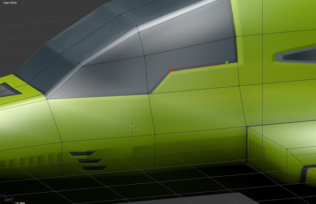
Now I want to create a small recess where the cockpit glass ends, so I'm using the bevel tool (CTRL+B) after I selected all the edges around the glass to duplicate them, creating small faces on the perimeter:

Now, with these faces selected, I can use CTRL+R to create a third edge in the middle, like this:

Now I have all the vertices I need to model the cockpit. Using scale and some manual tweaking I end up with these shapes:

The tricky part is to understand how big and deep these beveled lines have to be, in order to be visible when printed; it really depends on how big you're going to print it and the resolution of your printer.
You can have an idea by doing some simple math: I found out that the depth is about the 0.33% of the length of the ship. This means that if I print it 10cm long, the depth will be about 0.3mm; since I usually print with a resolution of 0.1mm it should be perfectly visible, but in case it isn't, I can tweak the vertices and print it again.
For some of the details I want them to be engraved or elevated from the main mesh. In these case it's even simpler; I can still cut the shape with the knife, and then use E (extrude) to move the new face inside or outside the model, creating the desired effect:

If the shape touches the half of the model, don't forget to delete the face I selected in the picture above, or it would be interpreted as a tiny "wall" in the center of your model.
There's not much else to say: now it's just a matter of time and patience, applying these two techniques on all the details you wish to add, until you're satified with the result. This is what I came up to:

Now I can apply the mirror modifier, so that it becomes a simple mesh again. Before doing so, make sure that all the vertices that should be in the center of the model have an X coordinate of 0.00. Sometimes, especially when using scale or rotation, it could happen that the vertices move away from their position, and in this case the resulting mesh is going to have holes in the middle.
Removing double vertices
After the application of the modifier, it's good practice to check for double vertices. These are duplicates vertices at the same location; even if they're invisible at first glance, they could result, again, in gaps or unwanted faces. This is the button to use (after selecting all the faces, pressing A):

In my case, I had 4 duplicate vertices. With 3d printing it's very important to have a manifold mesh This means that the mesh must be completely closed, without any gap. That's because the printer software has to know what is the "outside" of the model and what is the "inside". If there's a hole, it will see it all as a thin, open plane, and wouldn't print it correctly. A fast way to check if the model is manifold is go to vertex editing, deselect all vertex (press A to select all, and A again to deselect all), and then use CTRL+ ALT + SHIFT + M. (You will need at least 3 hands to do it!). This will select all the non-manifold vertices, so that you can check them and correct the issues: it is usually due to duplicate vertices, or hidden faces.
If you look at my model after I selected the non-manifold vertices, you can see I still have some (the yellow ones):

This happens because I have some intersecting faces (I created the cylinders for the engines and I simply intersected them with the main mesh, without connecting the polygons). I could fix it using the boolean modifier, but in this case I prefer to leave them as they are to don't overcomplicate the model, and try to use the auto-correction of the dedicated 3d-printing software to get the job done. Remember, you can use this trick only if you know the 2 shapes are completely intersecting, without leaving any open hole.
Adding the stand
Moving to the stand, I started with a simple box placed under the ship, extruded and stretched until I'm fine with the shape; for the base I decided to pay homage to the game concept using an hexagonal pattern (it's just a cylinder with only 6 vertices), then I rotated the ship slightly to make its nose point up, up and away!, and I rotated the upper part of the stand accordingly. As I did for the motors, I will not connect the stand with the bottom of the ship; I will just move it up until they intersect.

When you're placing the stand and deciding the size of the base, be careful of the weight distribution of your model: if you make it to small or place it outside the center of mass your miniature could fall on one side. In my case the majority of weight is placed on the rear side, so I'm going to place the stand under that part.
This is the final model I'm going to print:

In the next post we're going to explore the softwares used to check and repair the mesh, and to convert it in a printable model.