Through this article, a programmable components from files will be described to generate a sinusoïde, on the basis of points previously recorded in a file.
Reading initial data: we can, for example, read the contents of a memory or a coefficient table of a complex operator such as a sinusoïde.
Writing simulation results: You can, for example, ask for the output of the simulation of a model to be written to a file.
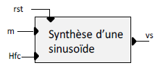
We want to describe a signal synthesis block to generate a sinusoïde, on the basis of points previously recorded in a file, having the following configuration:
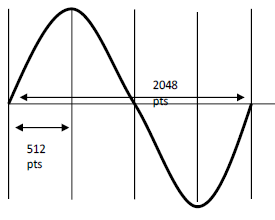
The values are generated via four quadrants of 512 points each, thus making it possible to reduce the number of samples to be stored.
The figure below shows the principle of signal generation that we want to develop with a state machine:
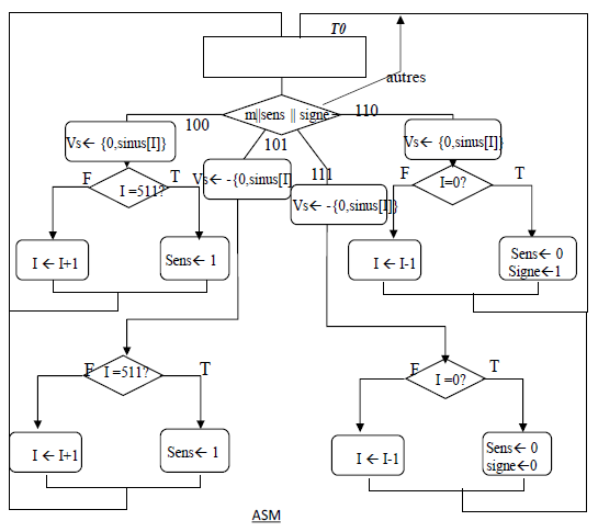
It has for symbol:
A variable I serving as a counter and pointing to the value of the output signal is used. The coefficients of the sinus are in ascending order in the first quadrant of the sinusoid, then in descending order in the second quadrant. From the third quadrant, they are negative. We therefore recommend the same order as above, ascending then descending. We thus have I, incremented and decremented alternately for each quadrant. For this, we use two other variables. The first is the direction variable, used to identify the direction of change in the table. We thus have 0 for an incrementation of the counter and 1 for a decrementation of the variable I. Finally, the sign variable is used to identify the sign that will be applied to the output: 0 positive, 1 negative.
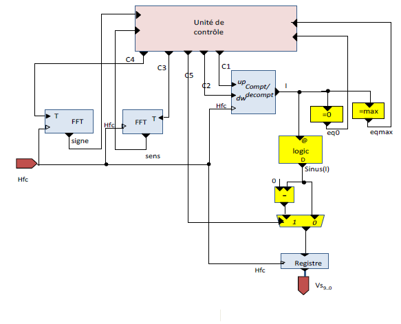
We thus have the architectural description of the sinus wave generator as follows:
The 512 values forming a sinus quadrant are generated using a python-type program. These values are represented, which will allow values from 0 to 500 tens of mV to be expressed.
We thus have the following program:
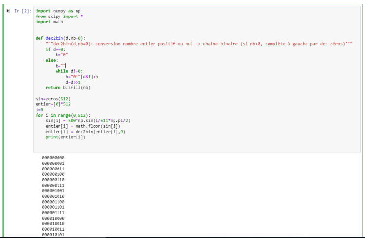
We have the following code implemented:
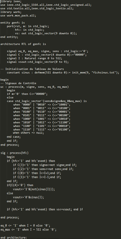
gen_fc.vhd
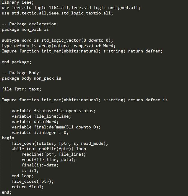
pack.vhd
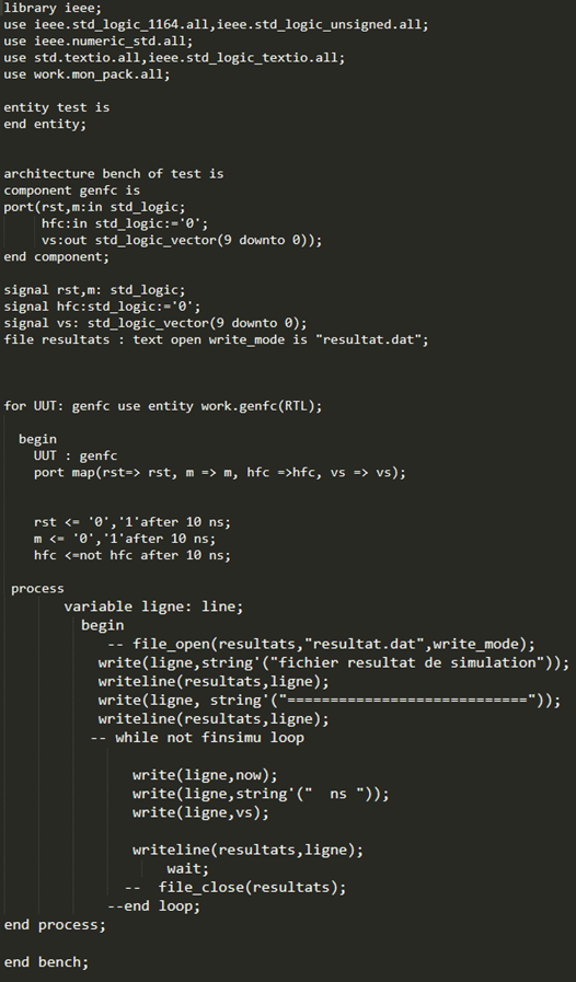
test.vhd
We test our RTL description and we get the following simulation:
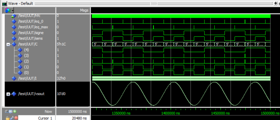
We have the generated sinusoid.
Through this article, a programmable components from files has been described to generate a sinusoïde, on the basis of points previously recorded in a file.
This article is part of my Electronics posts blog, in which you can find few articles about things i learnt in my post-graduated school :)